Multiple Choice
Identify the
choice that best completes the statement or answers the question.
|
|
|
SolidWorks Chapter 2 Test
|
|
|
1.
|
a. | Extruded Cut Feature | c. | Fillet Feature | b. | Mirror Feature | d. | Chamfer Feature |

|
|
|
2.
|
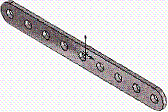
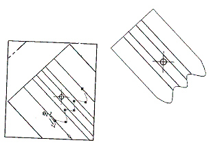
Identify the following feature icon  . a. | Extrude Boss/Bass feature | c. | Circular Pattern
Feature | b. | Round Pattern Feature | d. | Chamfer Feature |
|
|
|
3.
|
Identify the following feature icon  . a. | Hole Wizard Feature | c. | Circular Pattern Feature | b. | Simple Hole
Feature | d. | Top
feature |
|
|
|
4.
|
Identify the following Feature Icon  . a. | Shell Feature | c. | Round Feature | b. | Loft Feature | d. | Rib Feature |
|
|
|
5.
|
Identify the following feature icon . .
a. | Shell Feature | c. | Round
Feature | b. | Loft Feature | d. | Revolved Cut
Feature |
|
|
|
6.
|
. Identify the number of instances in the
illustrated model.
|
|
|
7.
|
Identify the Sketch plane for the Extrude 1
feature.

a. | Top Plane | c. | Right
Plane | b. | Front Plane | d. | Left
Plane |
|
|
|
8.
|
Identify the following sketch entities icon . .
a. | Center Arc Tool | c. | 3
Point Arc Tool | b. | Tangent arc
Tool | d. | Point Arc Tool |
|
|
|
9.
|
Identify the following sketch entities
icon . .
a. | Center Arc Tool | c. | 3
Point Arc Tool | b. | Tangent Arc
Tool | d. | Point Arc Tool |
|
|
|
10.
|
Identify the following sketch entities icon . .
a. | Centerpoint Arc Tool | c. | 3 Point Arc Tool | b. | Circle
Tool | d. | Singlepoint Arc Tool |
|
|
|
11.
|
A fully defined sketch is displayed in what
color?
a. | Blue | c. | Red | b. | Black | d. | None of the
listed |
|
|
|
12.
|
What symbol does the FeatureManager display before
the Sketch name in an under defined sketch?
a. | (-) | c. | (+) | b. | (?) | d. | No symbol |
|
|
|
13.
|
Which is not a valid drawing format in SolidWorks?
a. | *.tif | c. | *.dwgg | b. | *.jpg | d. | *.dxf |
|
|
|
14.
|
Which is a valid assembly format in
SolidWorks?
a. | *.tiffe | c. | *.assmy | b. | *.jpgg | d. | *.stl |
|
|
|
15.
|
Identify the following Drawing View icon  . .
a. | Projected View | c. | Cut
View | b. | Trim View | d. | Crop
View |
|
|
|
16.
|
Identify the following Drawing View icon . .
a. | Section View | c. | Break
View | b. | Broken View | d. | Aligned Section
View |
|
|
|
17.
|
Identify the following Drawing View icon  . .
a. | Projected View | c. | Break
View | b. | Standard 3 View | d. | Aligned Section
View |
|
|
|
18.
|
Identify the illustrated Drawing View.
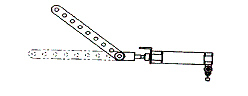
a. | A: Projected View | c. | Extended View | b. | Alternative
Position View | d. | Aligned Section View |
|
|
|
19.
|
Identify the illustrated Drawing view.
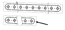
a. | Crop View | c. | Broken-out Section View | b. | Break
View | d. | Aligned Section View |
|
|
|
20.
|
Identify the illustrated Drawing view.
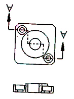
a. | Section View | c. | Broken-out Section View | b. | Crop
View | d. | Aligned Section View |
|
|
|
21.
|
Identify the view procedure. To create the
following view, you need to insert a:
a. | Rectangle Sketch Tool | c. | Open Profile: Circle | b. | Closed Profile:
Spline | d. | None of the above |
|
|
|
22.
|
the view procedure. To create the following view,
you need to insert a:
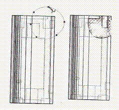
a. | Open Spline | c. | 3
Point Arc | b. | Closed Spline | d. | None of the
above |
|
|
|
23.
|
Identify the illustrated view type.
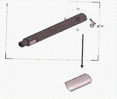
a. | Crop View | c. | Projected View | b. | Section
View | d. | None of the above |
|