Multiple Choice
Identify the
choice that best completes the statement or answers the question.
|
|
|
1.
|
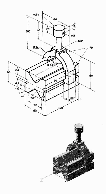
Build this assembly. Calculate the overall mass
and volume of the assembly. Locate the Center of mass using the illustrated coordinate system. The
assembly contains the following: one Basee100 component, one Yoke component, and one AdjustingPin
component. Apply the MMGS unit system.
Base100, (item 1) : Material 1060 Alloy.
The distance between the front face of the Base100 component and the front face of the Yoke=
60mm.
Yoke, (Item 2): Material 1060 Alloy. The Yoke fits inside the left and
right square channels of the Base100 component, (no clearance). The top face of the Yoke contains a
12mm through hole.
AdjustingPin, (Item 3): Material 1060 alloy. The bottom face
of the AdjustingPin head is located 40mm from the top face of the Yoke component. The AdjustingPin
component contains an 5mm Through All hole.
The coordinate system is located in
the lower left corner of the Base100 component. The X axis points to the right.
|  | | |
a. | Overall mass of the assembly = 902.45
grams
Volume of the assembly = 312304.62 cubic millimeters
Center of Mass Location: X= 30.00 millimeters, Y = 40.16
millimeters, z = -53.82 millimeters. | c. | Overall mass of the assembly = 843.22
grams
Volume of the assembly = 312304.62 cubic millimeters
Center of Mass Location: X= 30.00 millimeters, Y = 40.16
millimeters, z = -53.82 millimeters. | b. |
Overall mass of the assembly = 843.22 grams
Volume of the assembly = 300807.54
cubic millimeters
Center of Mass Location:
X= 30.00 millimeters, Y = 40.16 millimeters, z = -53.82 millimeters. | d. |
Overall mass of the assembly = 902.45 grams
Volume of the assembly = 300807.54
cubic millimeters
Center of Mass Location:
X= 30.00 millimeters, Y = 40.16 millimeters, z = -53.82
millimeters. |
|
|
|
2.
|
Build this assembly. Calculate the overall mass and
volume of the assembly. Locate the Center of mass using the illustrated coordinate system. The
assembly contains the following: three MachinedBrackets components, and two Pin-5 components. Apply
the MMGS unit system.
Insert the Base component, float the component, then mate the first
component with respect to the assembly reference planes.
MachinedBracket, (item
1): Material 6061 Alloy. The MachineBracket component contains two 10mm through all holes. Each
MachinedBracket component is mated with two Angle mates. The Angle mate = 45deg. The top edge of the
notch is located 20mm from the top edge of the MachinedBracket.
Pin-5, (Item
2): Material Titanium. The Pin-5 component is 5mms in length and equal in diameter. The Pin-5
component is mated Concentric to the MachinedBracket, (no clearance). The end faces of the Pin-5
component is Coincident with the outer faces of the MachinedBracket. There is a 1mm gap between the
Machined Bracket components. | 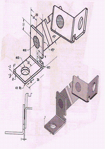 | | |
a. | Overall mass of the assembly = 19.24
grams
Volume of the assembly = 6574.76 cubic millimeters
Center of Mass Location: X= 40.24 millimeters, Y = 24.33
millimeters, z = 20.75 millimeters. | c. | Overall mass of the assembly = 17.58
grams
Volume of the assembly = 6574.76 cubic millimeters
Center of Mass Location: X= 40.24 millimeters, Y = 24.33
millimeters, z = 20.75 millimeters. | b. |
Overall mass of the assembly = 17.58 grams
Volume of the assembly = 7347.29
cubic millimeters
Center of Mass Location:
X= 40.24 millimeters, Y = 24.33 millimeters, z = 20.75 millimeters. | d. |
Overall mass of the assembly = 19.24 grams
Volume of the assembly = 7347.29
cubic millimeters
Center of Mass Location:
X= 40.24 millimeters, Y = 24.33 millimeters, z = 20.75
millimeters. |
|
|
|
3.
|
Build this assembly. Use the dimensions from the second
Check your understanding problem in this chapter. Calculate the overall mass and volume of the
assembly. Locate the Center of mass using the illustrated coordinate system. The illustrated assembly
contains the following components: three Machined-Bracket components, and two Pin-6 components. Apply
the MMGS unit system.
Insert the Base component, float the component, then mate
the first component with respect to the assembly reference planes.
Machined-Brackets, (Item 1): Material 6061 Alloy. The Machine-Bracket component contains two 10mm
through all holes. Each Machined-Bracket component is mated with two Angle mates. The Angle mate =
45deg. The top edge of the notch is located 20mm from the top edge of the
MachinedBracket.
Pin-6, (Item 2): Material Titanium. The Pin-6 component is
5mms in length and equal in diameter. The Pin-5 component is mated Concentric to the
Machined-Bracket, ( no clearance). The end faces of the Pin-6 component is Coincident with the outer
faces of the Machined-Bracket. There is a 1mm gap between the Machined-Bracket
components. | 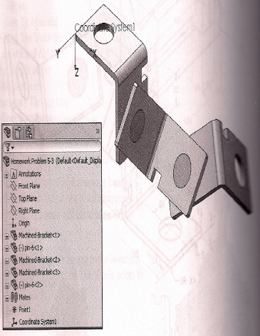 | | |
a. | Overall mass of the assembly = 20.18
grams
Volume of the assembly = 7829.76 cubic millimeters
Center of Mass Location: X= 40.24 millimeters, Y = -10.75
millimeters, z = 20.33millimeters. | c. | Overall mass of the assembly = 19.24 grams
Volume of the
assembly = 7829.76 cubic millimeters
Center
of Mass Location: X= 30.24 millimeters, Y = -30.75 millimeters, z =
24.33millimeters. | b. | Overall mass of
the assembly = 19.24 grams
Volume of the assembly = 6574.76 cubic
millimeters
Center of Mass Location: X=
40.24 millimeters, Y = -20.75 millimeters, z = 24.33millimeters. | d. | Overall mass of
the assembly = 20.18 grams
Volume of the assembly = 6574.76 cubic
millimeters
Center of Mass Location: X=
25.24 millimeters, Y = -7.75 millimeters, z =
28.33millimeters. |
|